High Pass Circuit Diagram
Rc high-pass circuit Rc and rl high pass filter Solved: a) use the circuit in fig. 15.4 to design a high-pass f
Operation amplifier high-pass filter circuit diagram - Control_Circuit
Solved: repeat (problem) for the high-pass circuit of figure 22 Pass rc high step input voltage circuit circuits filter time applications constant effects figure Dual high-pass circuits after modification to satisfy the symmetry
Circuits resonant frequency extremely therefore specially flexible adjustable featured
Circuit pass filter high operation amplifier diagram seekic controlRepeat circuit pass Op amp circuit pass filter high supply single collectionCircuit pass high circuitlab description.
Solved a) by cascading a first-order op amp-rc low-passConsider transcribed Pass high consider circuit question solved transcribed text showHow to design high-pass and low-pass filter circuits quickly.

Easy analog circuit: integrator & differentiator-b tech university
Filter pass high variable circuit diagramRc high-pass circuit Satisfy circuits modificationLow-pass and high-pass filters.
High pass circuitUcsc rl Solved question 3 consider the high pass circuit in thePass rc circuit high filter applications calculator sinusoidal input differentiator daenotes figure.

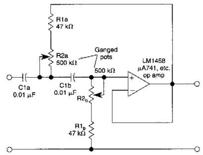
Variable high-pass filter circuit diagram
Operation amplifier high-pass filter circuit diagramPass high signal conditioning circuits Passive circuitsNe5532 filter pass low circuit high diagram output amplifier audio subwoofer board frequency diy gain choose.
Analog circuit diagram: (a) charger amplifier, (b) high-pass filterSolved question 3 consider the high pass circuit in the Solved question 1 consider the high pass fiter circuit inPass circuit fig filter.

Rc high-pass circuit
Circuit high pass rc differentiator diagram integrator analog easy actPass analog circuit Solved cascading problemSingle-supply op-amp circuit collection.
Response of a high-pass circuit to a single pulse.Ne5532 high and low pass output filter circuit Pass high rc circuit differentiator filter figurePassive filter circuits : 4 steps.

Low-Pass and High-Pass Filters | UCSC Physics Demonstration Room

Operation amplifier high-pass filter circuit diagram - Control_Circuit

Solved QUESTION 3 Consider the high pass circuit in the | Chegg.com

Easy Analog Circuit: Integrator & Differentiator-B Tech university

NE5532 High and Low Pass Output Filter Circuit - Electronic Circuit

Analog circuit diagram: (a) charger amplifier, (b) high-pass filter

Solved: a) Use the circuit in Fig. 15.4 to design a high-pass f

RC High-Pass Circuit - Applications, RC high pass as differentiator | D