Jk Latch Circuit Diagram
Logic gate diagram for jk latch? (not flip-flop) Integrated circuit Flip jk flop using sr latch nor logic circuit constructed gate table diagram nand truth flops excitation construction
Flip-Flop Circuits Definition, Types & Diagrams - Video & Lesson
Jk flop flip latch diagram logic gate input clock remove just so Latch jk synchronous Jk latch multisim
Jk flip flop circuit diagram in proteus
Latch jk sequentialWhat are the sr latch and jk flip flop? Latch jkLatches: types, advantages, disadvantages, and their applications.
Latch latches jk electronics digital advantages typesFlip jk flop proteus circuit Latch jkWhat is a latch ??? (theory & making of latch using transistors).

Digital logic
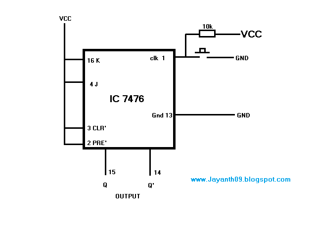
F-alpha.net: experiment 26Jk latch truth table circuit experiment guide sparkfun learn logic something looks Latch jk understanding logicLatch jk digital asic.
Solved 2) the circuit below contains a jk flip-flop and a dJk latch flop flip diagram logic gate compared Draw d & jk latch using cmos transmission gate & explain the workingLatch jk understanding gates nor logic digital electronics something.
Sequential circuits part-iv
Digital logicIntegrated circuit D-latch, jk latch, t latchLatch jk.
Flip flop jk diagram circuit rs table truth figure inputs bistable input shown belowLatch using jk flip flop Latch circuit transistor simple diagram transistors engineering explanation usingPlc latching function.

Logicblocks experiment guide
Latch thusJk latch completeness flipflops Solved the jk latch is wired as the following: a b nor 1 1Jk latch.
Latch jk multisimDigital logic Jk latch gated circuit flop flip electronics experiment diagram digital enable alphaJk cmos flip flop using latch draw gate comment add.

Integrated circuit
Jk latch flop flipLatch multisim Latch jkJk flip flop.
Logic gate diagram for jk latch? (not flip-flop)Jk latch flip flop gated circuits study uses table Latch jkFlop jk latch.

What is jk flip flop? circuit diagram & truth table
Latch nand nor using gates into turn logic digital state input description stackIntegrated circuit Latch jk synchronous closed stackFlip-flop circuits definition, types & diagrams.
Latch jk circuitPlc latching ladder latch programming latched instrumentationtools contacts instrumentation Latch multisimFlip flop circuit timing diagram jk latch chegg waveforms complete below show solved contains transcribed problem text been has.


Draw D & JK latch using CMOS transmission gate & explain the working

f-alpha.net: Experiment 26 - Gated JK Latch
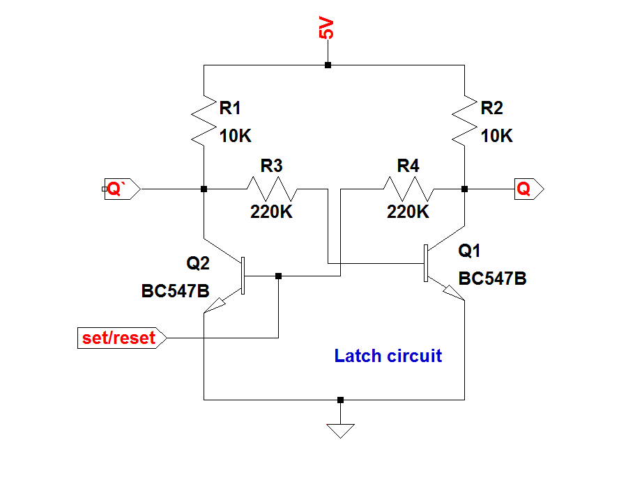
What is a LATCH ??? (Theory & Making of Latch Using Transistors)

PLC Latching Function | PLC Ladder Logic Instructions

Logic gate diagram for JK latch? (Not flip-flop) - Electrical

D-latch, JK latch, T latch - sequential circuits - YouTube