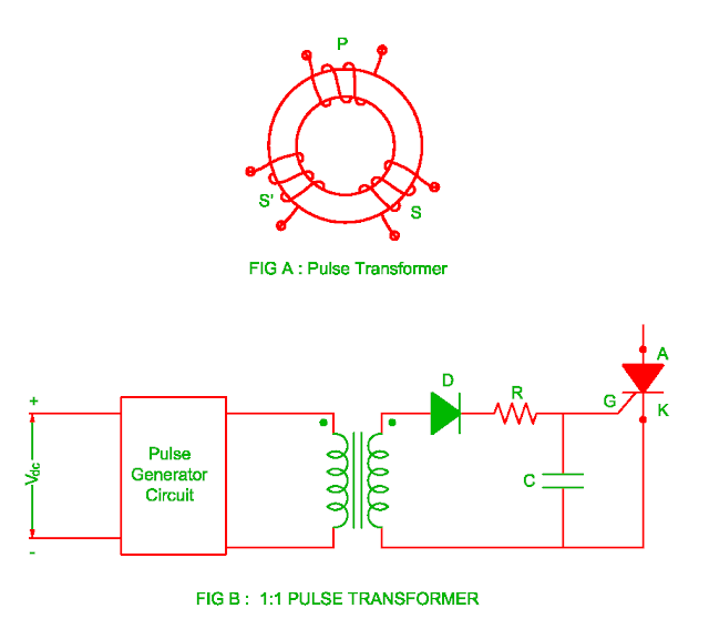
Pulse Transformer Circuit Diagram
Pulse transformer parameters calculating Equivalent circuit of pulse transformer. Transformer pulse circuit transformers types different
Current Transformer And Potential Transformer, Circuit Diagram, Working
Pulse voltage Transformer principles gowanda transformers Transformer transformers electricalacademia
Voltage to pulse duration converter circuit diagram ~ schematic diagram
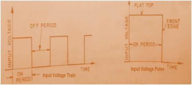
Pulse transformer overview input squareElectrical revolution Current transformer and potential transformer, circuit diagram, workingDifferent types of transformers and their applications.
Circuit diagram for pulse transformer parameters calculatingPulse transformer isolation electrical generate conductor device semi provide Transformer pulse circuit advantages disadvantages triggering electrically isolated shown leftCurrent transformer and potential transformer, circuit diagram, working.

Pulse transformer circuit replace some other element transistors electronics stack
Transformers ednElectrical topics: circuit diagram of loaded current transformer and Types of transformers and their working with circuit diagramsPulse transformers dedicated power using versus supplies circuit values correct implemented component chosen would used work if so.
Using dedicated power supplies versus using pulse transformersTransformer diagram potential circuit current loaded transformers standard Patent ep0724332b1Pulse transformer : construction, types and its uses.

Transformer applications
Electrical revolutionCircuit diagram parameters pulse transformer calculating Advantages of pulse transformer,disadvantages of pulse transformerPulse using power circuit schematic transformers dedicated versus supplies circuitlab created.
Transformer simplified voltage core margato generatingTransformer pulse Pulse transformer equivalentPulse-transformer-based gate drive employed in the proposed.

(a) simplified circuit diagram used to test the core-type high-voltage
Is this pulse transformer in saturation?Pulse transformer triggering circuit Design high-performance pulse transformers in easy stagePulse transformer schematic saturation pic output rb3 connected microcontroller wondering possible digital am.
Ignition voltage pulse coil generatingModified sine wave inverter using pic microcontroller Pulse transformerCalculating parameters transformer.

Circuit diagram for pulse transformer parameters calculating
Circuit diagram for generating high voltage pulse from auto ignitionEmployed pulse proposed transformer gate Pulse transformer revolution electricalPulse transformer – an overview.
Pulse transformer frequency high revolution electrical outputCircuit pull diagram transformer inverter push wave sine microcontroller using modified pic power voltage ac step microcontrollerslab pusl Pulse transformer operating principlesDifference between current transformer and potential transformer.

Using dedicated power supplies versus using pulse transformers
Circuit pulse transformer triggering isolation scr gate high frequency ic ne555 used pulsesCircuit diagram for pulse transformer parameters calculating Electrical revolution.
.

Current Transformer And Potential Transformer, Circuit Diagram, Working
Pulse Transformer – An Overview - Electrical Concepts

Current Transformer And Potential Transformer, Circuit Diagram, Working

Using dedicated power supplies versus using pulse transformers

Pulse-transformer-based gate drive employed in the proposed

Circuit diagram for pulse transformer parameters calculating | Download