Edge Triggered D Flip-flop Circuit Diagram
Negative edge triggered d flip flop circuit diagram Solved question 1 referring to the positive-edge triggered d Digital logic
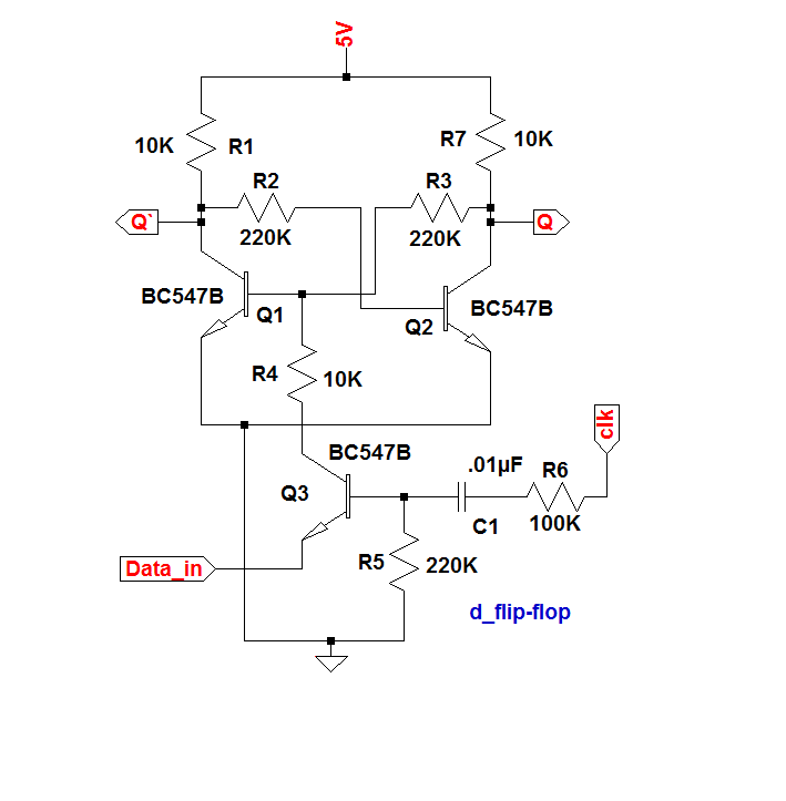
Proposed Positive edge D flip flop Circuits | Download Scientific Diagram
Flip flop triggered circuit flops electronics Logic flip flipflops flop triggered negative circuits referred flops Flip discrete flop circuit using flops diagram transistors explanation hackaday io
Edge flip flop timing triggered diagram negative
Flop flip triggered circuit nand implementationTriggered flop slave Negative flop triggered chegg convertRs flip flop diagram.
Flip edge triggered flop positive flops computer engineering state lecture machines monday week ppt powerpoint presentationEdge-triggered d flip-flop Flop flip jk circuit logic sequential inputs bcis notes bistableFlip flop edge triggered circuit circuits simulation simulator.

Proposed positive edge d flip flop circuits
Flip flop circuit diagram edge triggered block sequential blocks unit building upscfever truth table flops elements storage logical organization computerFlipflops logic circuits gates are referred to as Flip flop edge triggered circuit trigger logic digital approach negative using gates stackWhat is a d flip-flop ??? (using discrete transistors).
Digital logicSolved for a positive-edge-triggered d flip-flop with inputs Negative edge triggered d flip flop circuit diagramCircuit design.

Negative edge triggered d flip flop circuit diagram
Flop flip triggered positive sponsored mikroraFlip flop edge triggered circuit nand positive input logic type gates circuits create there clock coupled cross electronics flipflop schematic J-k flip-flop and t-flip-flop || sequential logic || bcis notesFlip flop edge triggered positive timing jk diagram output inputs shown digital logic sketch clk below question solved.
Postive edge triggered d flipflopFlipflop edge triggered positive postive electronics lab community pe example projects Flip flop d edge triggeredTiming diagram for a negative edge triggered flip flop.
Flop flip cmos implementation using triggered edge diagram logic circuit implement provides trying wikipedia following am search google
Storage elements : flip flopsFlop flip triggered eeweb Flop circuits proposed.
.


Timing Diagram for A Negative Edge Triggered Flip Flop - YouTube

J-K Flip-flop And T-Flip-flop || Sequential Logic || Bcis notes

circuit design - CMOS implementation of D flip-flop - Electrical

Solved QUESTION 1 Referring to the positive-edge triggered D | Chegg.com

Negative Edge Triggered D Flip Flop Circuit Diagram - vayp-por

digital logic - what is the approach to design edge triggered d flip

Proposed Positive edge D flip flop Circuits | Download Scientific Diagram

Negative Edge Triggered D Flip Flop Circuit Diagram - vayp-por